To stake out a line
Before you start, configure your navigation display settings. You can stake relative to a DTM or the design elevation, if required.
-
To select the line:
- From the map, you can:
- Select the line and tap Stakeout.
- Select the two points that define the line, and then tap and hold in the map and select Stake out line.
- Double‑tap the line in the map.
TIP – When selecting a line to stake out from the map, tap near the end of the line that you want to designate as the start. Arrows are then drawn on the line to indicate the direction. If the direction is incorrect, tap the line to deselect it and then tap it at the correct end to reselect the line in the direction required. Alternatively tap and hold in the map and select Reverse line direction from the menu.
NOTE – If the line has been offset, the offset directions are not swapped when the line direction is reversed.
- From the menu, tap
 and select Stakeout / Lines. Tap
  next to the Line name field and select:
- List to view a list of previously defined lines to select from.
- Two points to define the line from two points.
- Azimuth to define the line by a start point and an azimuth.
- From the map, you can:
-
In the Stake field, select the method and then fill out the required fields. Refer to the Line stakeout methods below.
To select the station to stake, key it in, tap the Sta‑ and Sta+ softkeys, or tap
 next to the Station fields to select a station from the list. To select the start or end station, tap the Start station or End station softkey.
TIP – To customize the stations available for stakeout, tap
next to the Station field to view the Select station screen. See Stations available for stakeout.NOTE – If the Station interval value is null, no station labels are displayed. If the station interval is 0, the station labels for the start and end stations plus any PI, PC or PT stations are displayed. If the station interval is a numeric value, labels for all stations are displayed (depending on the zoom scale).
- To display the cut or fill relative to a surface during stakeout, enable the Cut/Fill to surface switch.
In the Surface field, select the surface file from the current project folder. Only surface files that are set to visible or selectable in the Layer manager are listed.
Alternatively, in the map select surfaces from BIM files. If you cannot select surfaces in the map, make sure the BIM file is set to selectable in the Layer manager. If the Selection mode button
 on the BIM toolbar is button is yellow
  , tap it and select Surface selection - Individual faces mode.
NOTE – You can select Surface selection - Whole object mode, but when using Whole object mode the software selects both the top and bottom surface and calculates the cut/fill to whichever surface you are closest to.
The Surface field indicates the number of surfaces you have selected in the map.
To select a different surface from the map, double-tap in the map to clear the current selection and then select the new surface.
If required, in the Offset to surface field, specify an offset to the surface. Tap
 to select whether the offset is to be applied vertical or perpendicular to the surface.
 To show the distance to the surface in the stakeout navigation screen, tap Options. In the Deltas group box, tap Edit and select the V. Dist surface at current position or the Perp. Dist to surface at current position delta. Tap Accept.
- To review the line definition, tap Details.
- Enter the Antenna height or Target height, the value of the station to be staked out (if any), and any further details, such as horizontal and vertical offsets.
- Tap Start.
-
TIP – When the stake method is Station on line, Station/offset from line or Skew offset, you can edit the elevation. To edit do this, press the Space key or tap
 and enter the new elevation value. The original design elevation is automatically restored as soon as you change the design or the section of the design being staked, or once you exit stakeout. To restore the original elevation during stakeout after you have edited it, press the Space key or tap and then tap next to the Design elevation field and select Reload original elevation.
 -
When the point is within tolerance, tap Measure to measure the point.
- Tap Accept to store the point.
- If you selected the View before storage option, the staked deltas you selected in the Stakeout options screen are shown. Tap Store.
- The software returns to the navigation screen or, if you selected multiple items to stake out, the software returns to the Stake out items list.
Line stakeout methods
TIP – When staking a station or staking to the line you can tap another station or line in the map to change what you are staking, and the stakeout details in the adjacent panel update to reflect the new selection.
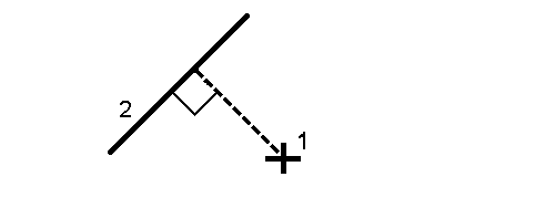
Measure your position (1) relative to a defined line (2).
Stake out the distance along a defined line (1) at the distance interval (2). The distance and distance interval values are slope distances along the line, rather than horizontal distances. This method also enables positions on a vertical line to be staked.
NOTE – When staking using this method the station values display in the map are on the horizontal.

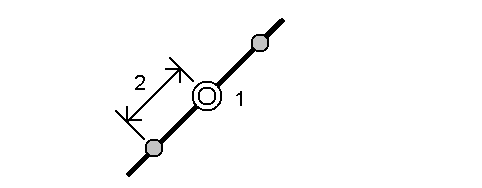
Stake out stations (1) on a defined line at the station interval (2) along the line.
Stake out a point (1) perpendicular to a station (3) on a defined line (2) and offset to the left or right by a horizontal distance (4). The design elevation of the point is the same as the elevation of the line at the selected station.
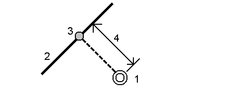
TIP – You can also apply a vertical offset.
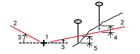
Measure your position relative to a slope (2) defined either side of a defined line (1). Each slope can be defined with a different grade (3).
Use the Slope left field and the Slope right field to define the type of grade in one of the following ways:
- horizontal and vertical distance
- grade and slope distance
- grade and horizontal distance
The software reports your position relative to the line and the vertical distance as a cut (4) or a fill (5) to the slope.
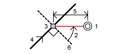
Stake out a point (1) at a skew (2) from a station (3) on a defined line (4) and offset to the left or right by a skew distance (5). The skew can be defined by a forward or backward delta angle to a line (6) at right angles to the line being staked, or the skew can be defined by an azimuth. The diagram shows a point defined by a skew forward and offset to the right.
The elevation for the point can be defined by:
- Slope from line – the elevation is computed by a slope from the elevation of the line at the entered station
- Delta from line – the elevation is computed by a delta from the elevation of the line at the entered station.
- Key in – the elevation is keyed in.
NOTE – If the line has no elevation, the elevation for the point must be keyed in.